
Reeves belt replacement is a requirement, as Reeves Motodrives transmit very high torques over a significant speed range. The Reeves variable speed belt that transmits these high loads is a heavy duty belt manufactured specifically for the task. It is constructed from heat and oil resistant neoprene, with the underside of the belt notched to permit easier flexing around the pulleys, which increases belt life.
Reeves Belt Replacement
Periodically, the Reeves belt will need to be replaced. Here are instructions for belt removal and replacement.
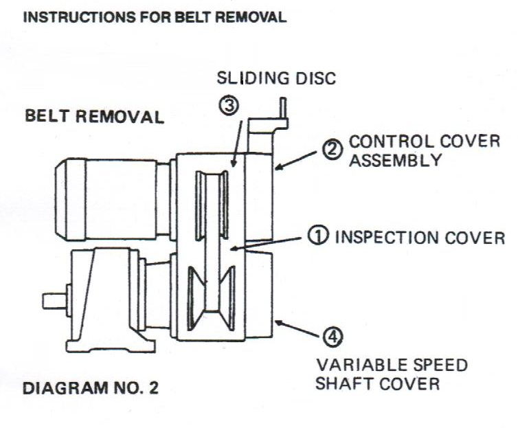
Instructions for belt removal
1. Run Motodrive to the high-speed position.
2. Remove the inspection cover (1).
3. Remove (4) screw holding Control Cover Assembly (2) and remove Control Cover Assembly from the Motodrive. Remove the Sloding Disc (3) (Thrust Bearing and Thrust Bearing Housing is attached to (3)). Leaved Fixed Disc in position.
4. Pull the loop of the belt over the end of the Fixed Disc Hub. (In some units it is necessary to remove the greaser first).
5. Remove the Variable Speed Shaft Cover (4).
6. Free the Belt from the Variable Disc (5).
7. Loop the Belt over the Variable Speed Shaft, and remover through inspection opening.
Belt replacement

Replacement is a reversal of the above procedure. On the 20A, 30 and 40 series Motodrive, when replacing the Control Cover Assembly, care must be taken to fit the prongs of the Shifting Yoke into the lugs of the Thrust Bearing Housing. On the 600 series Motodrive, care must be taken to insert the Guide Pin into the Control Housing. In all models except 20L ensure that the shifting yoke is properly seated on the shifting nut. On the 20L, when replacing the Control Cover Assembly care must be taken to fit the Pin in the Shifting Screw into the Lugs of the Thrust Bearing Housing.
When in doubt, contact us.